
Solar array model
- Example: PV module calculator
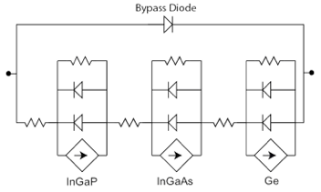
The ability to use Solcore to build a SPICE equivalent circuit allows entire PV systems to be simulated from the bottom up. Each photovoltaic solar cell is described using an equivalent circuit which can then be arranged in strings of series and parallel cells to represent the entire system. An example for a triple junction solar cell, complete with a bypass diode is shown in figure [fig:3J_equiv_curcuit]; this unit is the basic building block for a concentrator PV module.
The diode and resistance values for the equivalent circuit are determined from solar cell testing, while the current source is evaluated by integrating the product of the spectral irradiance (estimated using an appropriate radiative transfer code e.g. SPCTRAL2 or SMARTS) and the quantum efficiency which in turn can be calculated dynamically as a function of temperature by Solcore.
Since the entire module (and subsequently the system) is assembled from individual solar cell components, it is possible (and indeed, necessary) to distribute the component values to accommodate for manufacturing tolerances. This enables a close match between the modelled output power and that measured experimentally and has been used to determine how both aerosols and precipitable water affect the electricity yield from concentrator PV systems. Where system IV data is available, the emergence of electrical faults, (e.g. shunts or shading) can also be accounted for.
PV module solver functions
-
solcore.spice.pv_module_solver.solve_pv_module(solar_cell, options, totalcells=25, bias_start=0, bias_end=75, bias_step=0.1, jscSigma=0.0002, shading=None)[source]¶ Calculate the IV curve of a PV module made of a certain number solar_cells connected in series in a single string. A certain dispersion to the distribution of photocurrents among cells and shadowing losses can be added to ahoeve more realistic results.
Parameters: - solar_cell – A solar cell object containing all the junctions
- options – A state object with all the options needed to solve the solar cell IV
- totalcells – Total number of cells in a string
- bias_start – Initial voltage of the IV curve of the module
- bias_end – Final voltage of the IV curve of the module
- bias_step – Step for the bias
- jscSigma – Width of the distribution of short circuit currents around the ideal (eg: 0.02 = 2%). Default is set to 0.02% to aid convergence
- shading – Array containing the shading loses for each cell. It can be a 2D array (0 = no shading, 1 = full shading)
Returns: A tuple with the array of voltages, currents, a list with the Isc of each junction in each cell and the raw output from SPICE.
-
solcore.spice.pv_module_solver.spice_junction(jc, nc, isc, j01, j02, n1, n2, Eg, rsh)[source]¶ Creates the string representation in SPICE of the junciton defined by the input values.
Parameters: - jc – junction counter
- nc – node counter
- isc – Short circuit current
- j01 – Reverse saturation current corresponding to ideality factor n1
- j02 – Reverse saturation current corresponding to ideality factor n2
- n1 – Ideality factor, typically = 1
- n2 – Ideality factor, typically = 2
- Eg – Bandgap of the material the junction is made off
- rsh – Shunt resistance in the junction
Returns: A string representation of the junciton in SPICE